Can any of you recommend a tutorial or lab sheet or books that i can download it as my references. This nail artwork injects an enjoyable persona in you.

Hairpin Micro Strip Line Band Pass Filter Reflectionless Filter Design Simulation Results In Cst Youtube
DESIGN OF THE HAIRPIN BAND PASS FILTER A The design of band pass filter involves two main steps.
. Hairpin Filter Design Tutorial. Fill in the parameters as desired. Hence the hairpin bandpass filter is capable of passing the fre-quencies between range 3910 GHz and 4436 GHz and re-jects all other frequencies.
I need to know how to start the design what things i need to know before doing the design. The filters application is image rejection at the input of a synthesized block downconverter. Electronic filters are circuits which remove unwanted frequency components from the signal to enhance wanted ones.
Design of microstrip hairpin bandpass filter for 29 GHz 31 GHz s-band radar with defected ground structure January 2019 Malaysian Journal of. This makes the design compact. I need to design a microstrip hairpin stripline bandpass filter for UWB application.
One can use Agilent ADS or Microwave Office as RF design software tool for simulation and verifying the results. In this article 1GHz Hairpin type of BPFBand Pass Filter design is explained. To see the filter specification in iFilter double-click the stored wizard state iFilter_Hairpin under the Wizards node iFilter Filter Wizard node in the Project browser.
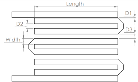
In hairpin filter space is saved by folding the resonator which is half wavelength long. Table 2 gives a comparison be-tween different research works. Figure 1 Printed Hairpin Filter with tapped input and output There are a number of papers in the literature describing design procedures for hairpin filters but they seem to be long on matrix math and short on practical dimensions.
Hpfilter design___NameValue designs a hairpin filter with additional options specified by name-value arguments. The advantage of hairpin filter over end coupled and parallel coupled microstrip is its low space utilization. Hairpin filters for the no-tune transverters 2.
Jul 20 2006 11 B. You can change the simulation parameters in the setup block. The layout is automatically created.
Simulation and measurement result shows that the proposed microstrip hairpin filter works at 923 MHz with bandwidth of 4 MHz from simulation result whereas from measureme nt r sult 75 MHz. The simulation results of the filter reach the design goals. The design hairpin resonator have a line width of 1mm and a sepration of 2mm between the two arm.
Filters are compact structures. Also the hairpin design is simple. By folding the parallel coupled half wavelength resonators in to u shape hairpin resonator is obtained.
Change the ResonatorOffset and FeedOffset and visualize it. 1 The first step is to select an appropriate low pass prototype. FilterFeedOffset 2 filterFeedOffset 2 5e-3.
1GHz Hairpin BPF design. For our example we are doing an LC filter Pi type where the first branch is a shunt Bessel type Low pass Third order scroll down to the Example for mathematical info and a corner frequency of 1 GHz. B Filter Design Specification- 1 Center.
By the way i will use the ansoft designer. How design hairpin filter hi everyone im going to design a hairpin bandpass filter. The response of the proposed filter is shown in fig4.
You can also shift the resonators and the feeds using the ResonatorOffset and FeedOffset properties of filterHairpin. The hairpin topology is a microstrip band-. Run the file to launch the openEMS analysis may take a while.
To run the openEMS simulation you need to install openEMS through octave or MATLAB and Paraview optional. The ouput is a S-parameter plot and the vtp and vtr files to do more post-processing. FilterResonatorOffset 0e-3 3e-3 5e-3.
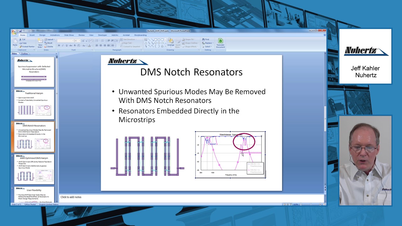
This video demonstrates a rapid and accurate flow for designing microstrip cross-coupled filters using Nuhertz filter solutions and NI AWR Design Environment. In this case the corner. A 37 to 42 GHz hairpin filter This filter was designed for a flat response over the 37 to 42 GHz band with low inser- tion loss and return loss better than 16 dB across the band.
Im new to this software cst microwave design so i really need help regarding this software. The concept of hairpin filter is same as parallel coupled half wavelength resonator filters. A band pass filter is designed to have a fractional bandwidth of 028 at a centre frequency of 25.
The filter is designed at center frequency of 58 GHz with a fractional bandwidth of 345. 2 The choice of type of response including pass band ripple order of filter and number of reactive elements will depends on the required specifications. This frequency is presenting for wireless LAN application and operates in the ISM band Industrial Scientific and Medical application.
Design of conventional hairpin filter Hairpin line filters are compact structures. The filter synthesis window will open. Hairpin Filter is one of the most popular microwave frequency filters because of it is compact and does not require grounding.
Passband Insertion Loss -3dB or better. A 37 to 42 GHz hairpin filter This filter was designed for a flat response over the 37 to 42 GHz band with low inser-tion loss and return loss better than 16 dB across the. With The sunshine pinkish and white shades blended with the seemingly washed on peach colored petals reveals as Should the sun has picked to glow on you and only you.
Note PCB components designed using the design function operate around the specified frequency with a 10-15 tolerance. By adding the via ground holes the di mension of the filter is reduced to 37. You can click the Generate Design button to see the filter synthesized.
This paper proposed a microstrip hairpin filter wi th via ground holes for 923 MHz RFID application. Design of a microstrip bandpass filter for 3 1 10 6 ghz. Ann modeling of microstrip hairpin line bandpass filter.
To allow for bending a sliding factor is introduced. Hairpin filter design tutorial Talk about a refreshing and shiny design. The figure depicts RF simulation circuit for 1GHz Hairpin BPF.
At the top menu under Tools click Filter synthesis. Im just a student without the knowledge of microstrip design. 1st Technique Conventional Hairpin configuration uses folding of the normal λ2 resonators into U shape.
2

Pdf Design And Analysis Of A Bandpass Hairpin Filter
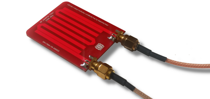
Charles Labs Hairpin Filter Design
Charles Labs Hairpin Filter Design
Design Example Nuhertz On Dms Hairpin Filter Youtube

Pdf Design And Simulation Of Hairpin Band Pass Filter For Different Substrate Engineering Research Publication And Ijeas Academia Edu
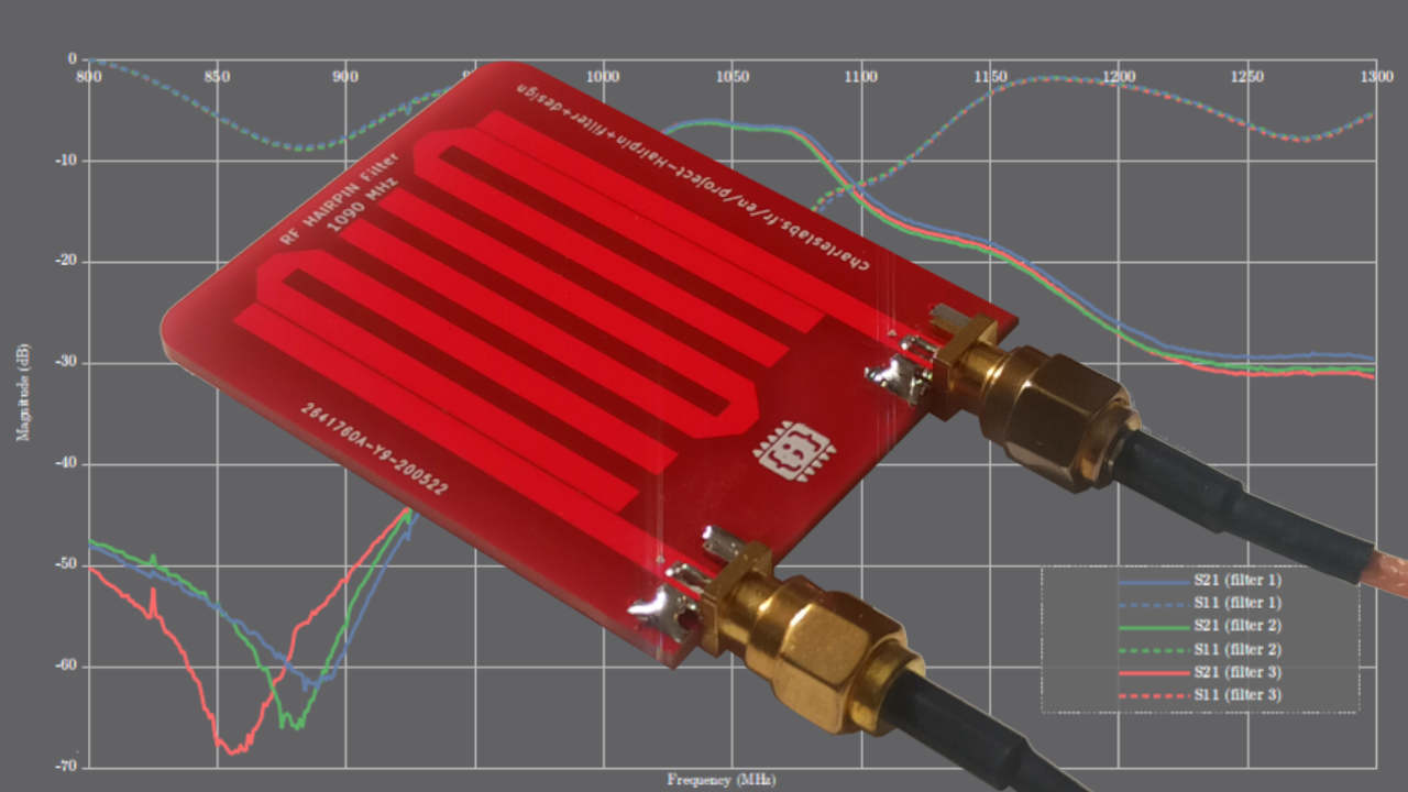
Charles Labs Hairpin Filter Design
Pdf Design And Analysis Of A Bandpass Hairpin Filter
0 comments
Post a Comment